Condenser Coils Explained: Types, Materials, and Industrial Applications
- Share
- publisher
- Boyi Cooling
- Issue Time
- Oct 28,2026
Summary
Condenser coils turn hot refrigerant vapor back into liquid, closing the loop in refrigeration and AC systems. This guide explains how they work across the desuperheating, condensing, and subcooling stages, compares L-type, V-type, and flat-type geometries, and sets out tube and fin material options from copper and aluminum to all-stainless. It also covers tube diameter, anti-corrosion treatments such as electrophoretic coating, and the parameters to specify when ordering a custom coil.
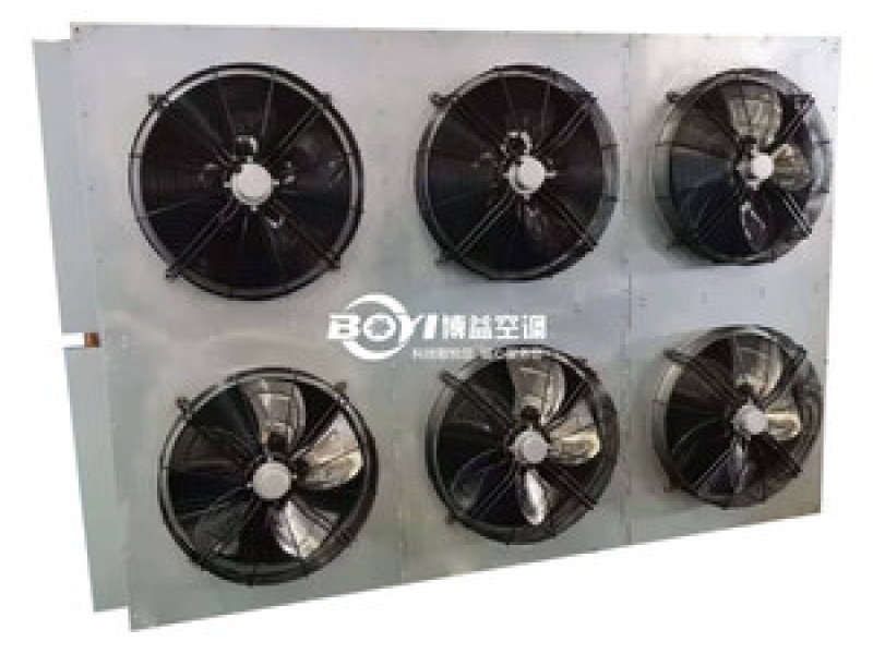
What a Condenser Coil Actually Does
Every vapor-compression refrigeration and air conditioning system contains four principal components, and the condenser coil is the one that makes the cycle possible. After compression, refrigerant leaves as a hot, high-pressure gas carrying the heat removed from the cooled space plus the heat of compression, and until that heat is rejected the cycle cannot continue. The condenser coil is the heat exchange surface where hot refrigerant vapor gives up its energy to a secondary fluid, usually ambient air or water, and changes phase back into a liquid.
That phase change makes condenser design fundamentally different from sensible heat exchange. A dry cooler only cools a fluid and never changes its state; a condenser manages a two-phase process where the heat transfer coefficient shifts as vapor becomes liquid, so geometry, tube diameter, fin surface, and circuiting must be engineered together.
How Condenser Coils Work: Three Distinct Stages
A coil does not simply cool the gas down. Refrigerant passes through three thermodynamically distinct zones, and a coil optimized for one zone but not the others loses capacity.
Desuperheating
Hot discharge gas enters at 70–90°C and cools to saturation. About 15–20% of total heat rejection happens here, and the vapor-side coefficient is poor, so this zone needs generous surface area.
Condensing
Between inlet and the collapse of the last vapor bubble, refrigerant releases latent heat at constant temperature. This is where 70–80% of the load is rejected, and film-wise condensation on the tube wall governs efficiency.
Subcooling
Liquid leaving the coil is cooled 3–8 K below saturation to prevent flash gas at the expansion valve. Every kelvin of subcooling directly increases usable system capacity.
Engineering note: Because condensate forms on the inner tube wall, the tube-side coefficient improves downstream. Coil circuiting exploits this by using fewer parallel circuits in the hot inlet passes and merging them as volume drops, holding velocity high while keeping pressure drop in budget.
Coil Types by Geometry: L-Type, V-Type, and Flat-Type
Geometry determines how much heat transfer surface fits into a given footprint, how air distributes across the fin block, and how the unit handles fouling and drainage. The three dominant configurations each solve a different space and airflow problem.
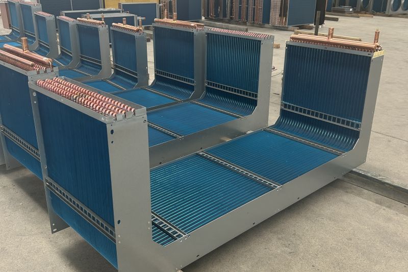
L-Type
Two coil blocks joined at 90° with airflow entering both faces and discharging upward. The shape delivers roughly 40% more surface area than a flat coil in the same footprint.
V-Type
Two coil banks arranged in a V over a common fan plenum. Air enters both inclined faces and is drawn into the plenum, evening out the velocity profile and lowering air-side pressure drop.
Flat-Type
A single planar coil bank mounted horizontally or vertically. Simplest to build and easiest to clean, it is preferred for ducted applications and existing-casing retrofits.
The trade-off is packing density against serviceability. A V-type packs the most capacity per square metre of ground space and typically cuts fan power by 8–15% versus an equivalent flat coil, because its effective face area is larger and air velocity across the fins is lower. But the V plenum makes the inner faces harder to reach for cleaning, while a flat coil gains full access to both faces, which matters in dusty or lint-laden environments.
Boyi Cooling builds all three geometries in copper, stainless steel, and mixed-material constructions. A rooftop plant room with limited footprint usually calls for L-type or V-type; a machine room with ducted discharge is normally cleaner with a flat coil. See our custom coil programme.
Tube and Fin Combinations
The tube carries the refrigerant; the fin multiplies the air-side surface. Their materials can be mixed or matched, and the combination drives corrosion resistance, thermal performance, first cost, and service life.
| Combination | Thermal performance | Corrosion resistance | Typical service |
|---|---|---|---|
| Copper tube + aluminum fin | Excellent, ~385 W/mK tube conductivity | Moderate; galvanic risk in salt air | Standard commercial AC and refrigeration |
| Copper tube + copper fin | Excellent and uniform | High; no bimetallic couple | Coastal, food processing, humid process air |
| Stainless tube + stainless fin | Lower, ~16 W/mK | Very high; chemical and high-temp resistant | Chemical plants, flue gas, aggressive atmospheres |
| Copper tube + hydrophilic aluminum fin | Excellent, improved wet-coil drainage | Moderate | High-humidity and cold-storage applications |
Copper tube with aluminum fin dominates the market because it delivers the best heat transfer per dollar. Aluminum fin stock is inexpensive, forms easily into collars that grip the tube for good mechanical contact and supports high fin density. The weakness is the galvanic couple: aluminum is anodic to copper, so if a conductive electrolyte film bridges the joint through salt spray, industrial sulphur, or persistent condensation, the fin corrodes sacrificially and can perforate within a few seasons.
All-copper construction removes the couple entirely. It costs more, but in coastal installations, food plants with washdown cycles, and any application where the coil stays wet, the extra service life justifies the premium. All-stainless gives up conductivity but survives environments where no copper alloy would last, including high-temperature flue gas recovery. Boyi Cooling builds all of the combinations above.
Tube Diameter: Capacity, Pressure Drop, and Charge
Tube diameter is one of the most consequential decisions in coil design. Three sizes cover most industrial work, each shifting the balance between surface area, refrigerant velocity, and internal volume.
| Outer diameter | Characteristic | Consequence |
| Ø9.52 mm (3/8") | Industry standard | Balanced capacity, pressure drop, and charge |
| Ø15.88 mm (5/8") | Large bore | High capacity per circuit, low pressure drop, larger charge |
| Ø7 mm | Small bore | Highest surface-to-volume ratio, reduced charge, higher pressure drop |
The physics rests on two competing requirements. Refrigerant-side heat transfer improves with velocity, so smaller tubes give better coefficients at a given mass flow, but pressure drop scales roughly with the inverse fifth power of diameter. A large-bore tube handles more mass flow at lower velocity and lower pressure drop, but its worse surface-to-volume ratio means more tube length for the same duty.
That last point matters more than it used to. With fluorinated gas phase-down schedules in force, minimizing charge is now a design objective in its own right, and Ø7 mm tubes can cut coil internal volume by 30–40% at similar capacity. Most industrial coils use Ø9.52 mm as the balanced default; Ø5/8" appears where capacity per circuit is the priority; Ø7 mm where charge reduction dominates.
Anti-Corrosion Treatments
In aggressive atmospheres, material selection alone is not enough. Surface treatments add a barrier over the entire coil assembly, and this is usually what separates a coil lasting four years from one lasting fifteen.
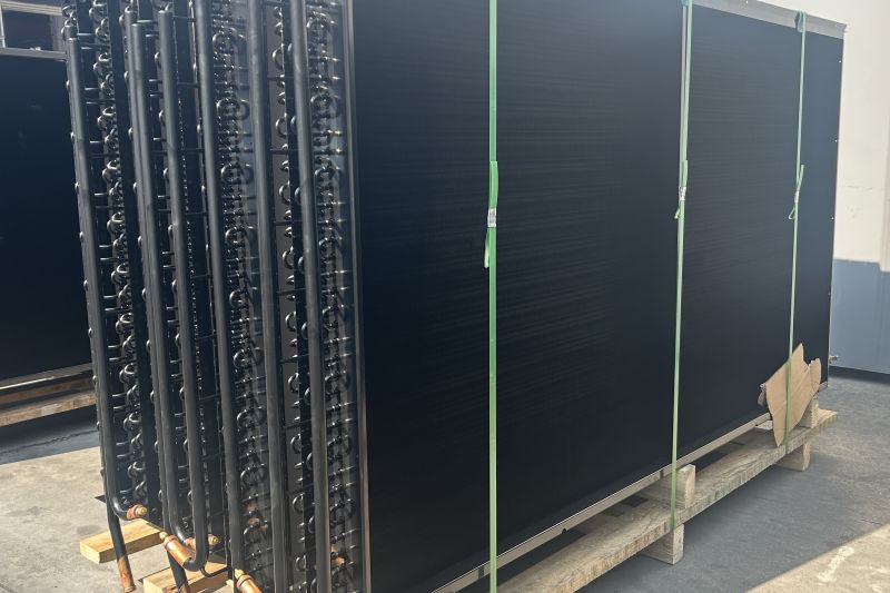
Electrophoretic Coating
The assembled coil is immersed in a bath and a DC field drives charged coating particles onto every surface, including fin edges, tube-to-fin joints, and internal crevices. Film thickness is uniform at 15–25 µm with no bridging between fins.
Barytic Coating
A barium-modified treatment formulated for strong chemical resistance, used where airborne acids, chlorides, or sulphur compounds attack standard organic films. Applied as a full immersion treatment after coil assembly.
GoldFin Treatment
A conversion coating applied to aluminum fin stock that resists the aluminium oxide bloom otherwise forming on bare fins in humid air, keeping the surface hydrophilic and maintaining drainage.
Two properties decide whether a coating helps or hurts. Coverage: a spray-applied film builds up on fin faces and bridges the gaps between fins, restricting airflow and cutting capacity, whereas electrophoretic deposition deposits on all surfaces at a controlled thickness and leaves fin passages clear. Thermal penalty: a 20 µm low-conductivity film typically costs 1–3% of capacity, a fair price for tripling service life, but it must be accounted for in the selection.
The practical rule at Boyi Cooling is to specify treatment by environment, not by default. A coil in a clean, dry inland plant room needs nothing beyond standard fin stock. The same coil installed 500 metres from a coastline, or in a food plant with daily chemical washdown, should be electrophoretically treated as standard practice. That is exactly the duty behind our electrophoretic anti-corrosion condenser.
Industrial Applications
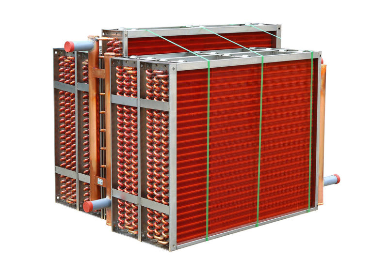
Condenser coils appear far beyond comfort cooling. The same physics applies wherever a process vapour must be turned back into a liquid.
| Industry | Duty and coil response |
|---|---|
| Refrigeration and cold storage | Condensers sized for low ambient operation with capacity control to hold head pressure in winter, with fin spacing widened to tolerate frost. |
| Commercial and industrial HVAC | Air-cooled chillers, rooftop units, and split systems working across a wide ambient range, with low fan power and low sound as priorities. |
| Power generation | Steam condensers operating under vacuum with large vapour volumes, using large-bore stainless or cupronickel tubes. |
| Chemical and process | Vapour recovery, solvent condensation, and gas cooling where chemical compatibility governs and cleanable construction matters. |
Boyi Condenser Cases
Ø9.52 mm Copper Tube L-Type Condenser
A cold-storage operator needed high capacity in a narrow service alley with vertical discharge. We built an L-type coil in Ø9.52 mm copper tube with aluminum fin at 10 FPI, sharing a common header and discharging upward into clear air, which also prevents hot air recirculating.
Electrophoretic Anti-Corrosion Condenser
For a coastal food plant with daily caustic washdown, bare aluminum fins had failed within three seasons. We rebuilt the coil in copper tube with copper fin and applied a full immersion electrophoretic treatment after assembly for uniform 20 µm coverage with no fin bridging.
Featured Product
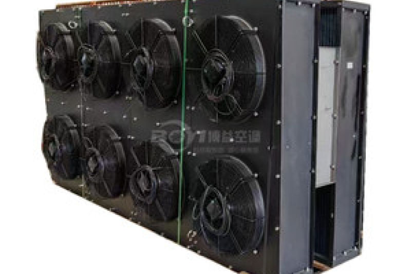
Selection Guide: What to Specify When Ordering
A custom condenser coil is only as good as the data behind it. Submitting a complete specification avoids the most common cause of underperformance: a coil correctly built but wrongly sized. These are the minimum parameters needed for an engineered selection.
With more than 20 years of thermal engineering experience, Boyi Cooling runs every enquiry through in-house selection software before a drawing is issued. Coils are exported to more than 30 countries and supplied with pressure testing and documentation. If your duty is unusual, that is the point, so send the parameters through and an engineer will size it directly.
Frequently Asked Questions
What is the difference between a condenser coil and a dry cooler?
A condenser coil condenses refrigerant vapour into liquid, so it handles a phase change and forms part of a refrigeration circuit. A dry cooler cools a single-phase fluid such as water or glycol and never changes its state. Condensers operate at higher pressures and are sized around latent heat rejection rather than sensible temperature drop.
Which tube diameter should I choose for a custom condenser?
Ø9.52 mm is the safe default and suits most refrigeration and air conditioning duties. Move to Ø15.88 mm when you need high capacity per circuit at low pressure drop, as in large process-gas condensers. Choose Ø7 mm when minimizing refrigerant charge matters most, and accept the higher pressure drop.
When is electrophoretic coating worth the cost?
Specify it whenever the coil faces salt-laden air, chemical vapours, continuous condensation, or cleaning agents. The treatment typically costs a small percentage of coil value and adds a 1–3% capacity penalty, but commonly multiplies service life threefold.
Key Takeaways
The condenser closes the refrigeration cycle, rejecting heat in three stages: desuperheating, condensing, and subcooling.
Geometry follows the site: L-type and V-type maximise capacity per footprint, flat-type maximises service access.
Material is an environment decision: copper plus aluminum for standard duty, all copper for wet or coastal duty.
Tube diameter trades capacity per circuit against charge and pressure drop.
Electrophoretic treatment extends coil life in aggressive atmospheres without bridging fins.
Need a Condenser Coil Engineered for Your Duty?
Boyi Cooling has been designing and manufacturing fin-tube heat exchange equipment for more than 20 years, supplying custom heat exchangers to customers in over 30 countries. From a standard Ø9.52 mm copper and aluminum condenser to an all-stainless electrophoretically treated coil, our engineers will size it, draw it, and build it to your duty.
Request a Custom Coil Quote About Boyi Cooling