


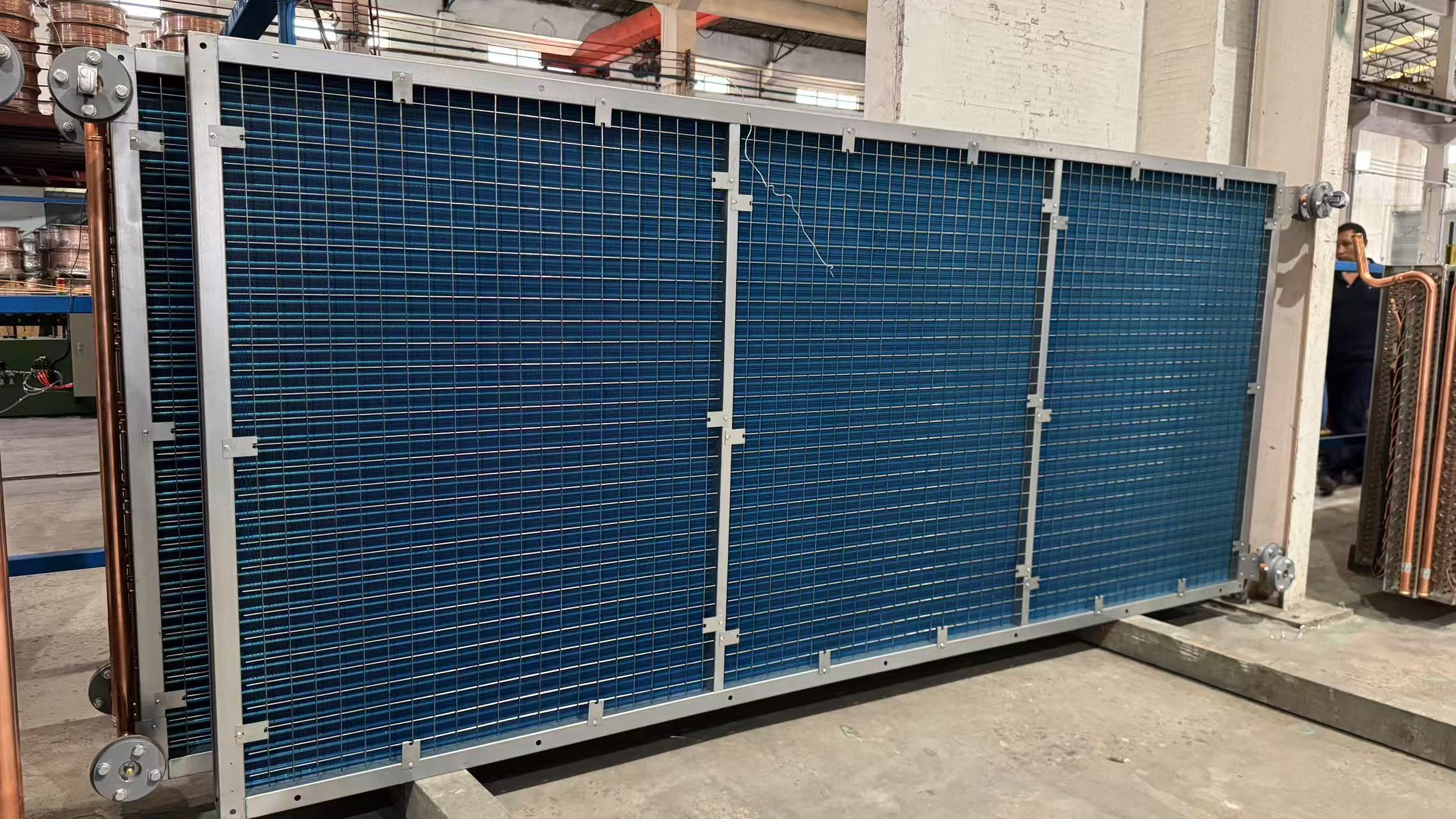
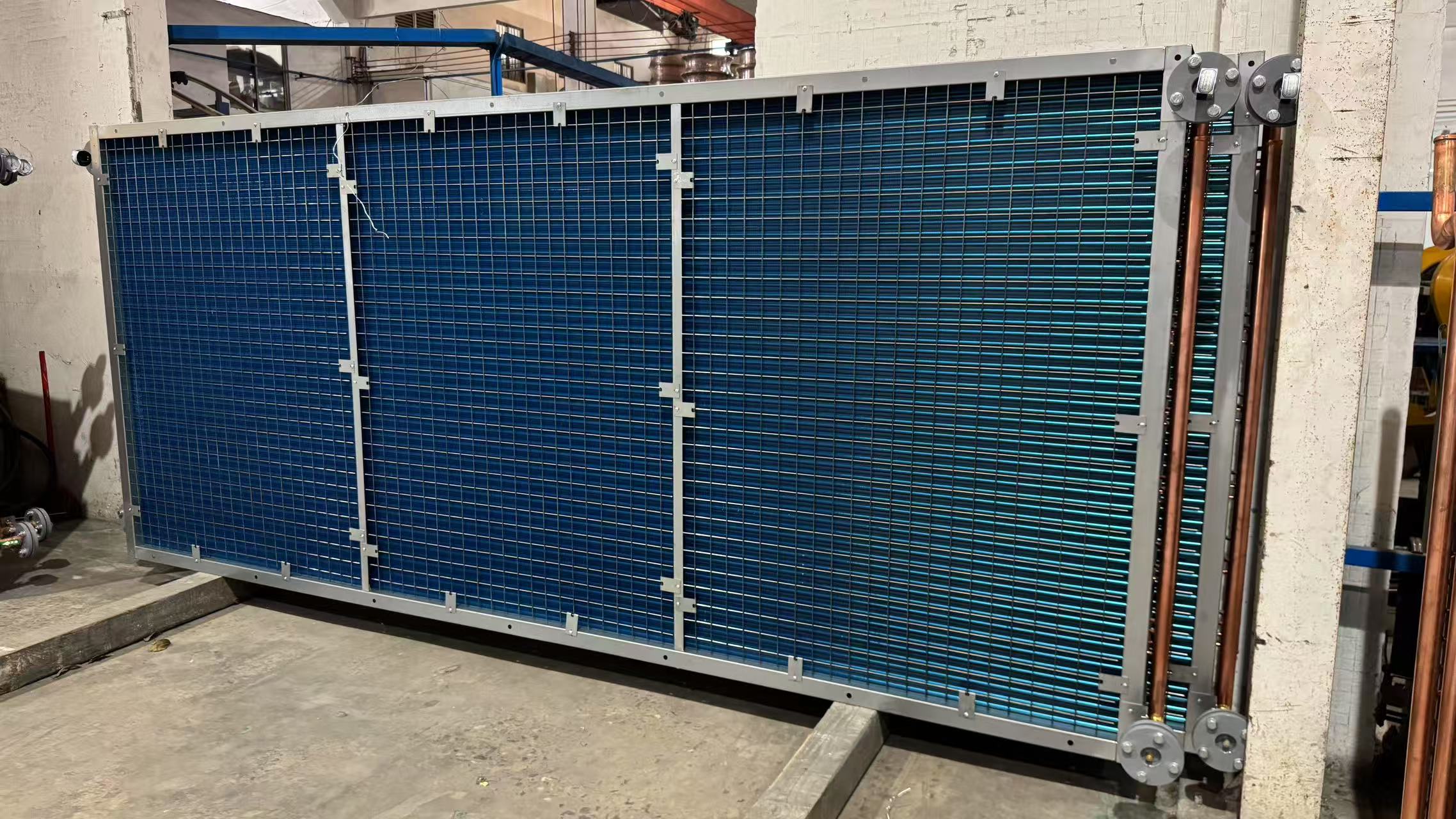
Custom Dry Cooling Coil for Cleanroom HVAC Cooling System
- Model
- BY-DCC
Item specifics
- Core Component
- Finned tube heat exchangers
- Tube Diameter
- 7mm, 9.52mm, 12.7mm, 15.88mm
- Casing Material
- Galvanized Steel, Aluminium, Stainless Steel
- Tube Material
- copper, stainless steel
- Fin Material
- aluminum, copper, stainless steel
Review
Description
Custom Dry Cooling Coil for Cleanroom HVAC Cooling System
There are significant differences in cleanliness standards, airflow organization and heat and humidity load management between Class 100 (ISO 5) and Class 1000 (ISO 6) cleanrooms, which directly affect the design parameters and system configuration of Dry Coil (DCC).
Below is a comparison of the core differences and data between the two when designing dry coils:
Differences in cleanliness and airflow requirements
1. Cleanliness Standards:
Class 100: ≥0.5μm ≤3,520 particles/m³ (ISO Class 5), unidirectional vertical flow to be maintained.
Class 1000: ≥0.5μm ≤35,200 particles/m³ (ISO Class 6) with non-unidirectional or mixed flow.
2. Number of air changes and surface air velocity:
Class 100: rely on FFU (fan filter unit) to realize high air velocity, the surface air velocity needs to be 0.25~0.45 m/s (the number of air exchanges is about 500~600 times/hour).
Class 1000: the number of air exchanges is 50~150 times/hour, and the FFU wind speed can be reduced to below 0.35 m/s.
Comparison of dry cooling coil design parameters
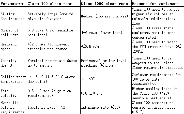
System configuration differences
1. Class 100 clean room:
1.1 DCC+FFU+MAU linkage: DCC only undertakes sensible heat load (wet load is handled by MAU), and needs to share the air conditioning system with the 10,000-level area.
1.2 Space limitations: DCC is often placed in the return air shaft, to avoid occupying the space of the FFU static pressure box, and reserve more than 1.5m maintenance channel.
1.3 Anti-condensation design: the temperature of chilled water is strictly higher than the dew point, and the water accumulation tray needs to be insulated and equipped with drainage monitoring.
2. Class 1,000 clean room:
2.1 Optional FFU/DCC or AHU/DUCT system: the latter is cheaper, but with high duct heat loss (high energy consumption).
2.2 Installation Flexibility: DCC can be arranged in the ceiling or sandwich wall without the need for high-level steel frame support.
Project Case Data of Dry Cooling Coils
1. Class 100 case (an electronics plant):
The 270m² hundred-level area adopts 552 sets of DCC, with a single cooling capacity of 53.3 kW, a temperature difference of 2℃ between inlet and outlet air, and the hydraulically balanced valve group adopts the same-program design (the difference in pressure loss is ≤5%).
2. Class 1000 case:
The 5,960m² thousand-level zone uses an AHU+FFU system with a DCC head wind speed of 2.3 m/s and a water flow rate of 0.9 m/s, resulting in a cooling redundancy coefficient of only 1.1 (lower than that of the hundredth level, which is 1.15).
Summarizing: core design differences
The design of dry coils in Class 100 cleanrooms requires greater redundancy and protection against hydraulic imbalance and condensation risk to accommodate their high air velocity and high heat load characteristics.
Class 1000 cleanrooms are more focused on cost and space optimization, allowing for a wider range of parameters.
The actual selection needs to be combined with the heat generation of process equipment (e.g. semiconductor equipment>pharmaceuticals) and the building structure (e.g. floor height limitations) to determine the comprehensive.
- Specifications can be tailored to suit each application, with different materials, sizes, noises and cooling mediums available.
- contact us


