Heating & Cooling Coils in HVAC Systems: A Technical Deep Dive
- Share
- publisher
- Boyi Cooling
- Issue Time
- Nov 2,2026
Summary
Heating and cooling coils do two opposite jobs in one finned-tube heat exchanger. This technical deep dive explains heating and cooling mode physics, multi-row circuiting design, material selection for dual-use duty, and a real Boyi Cooling greenhouse case pairing a 1-row heater with a 2-row cooler. Ideal for engineers specifying AHU, rooftop, greenhouse, and industrial HVAC coils.
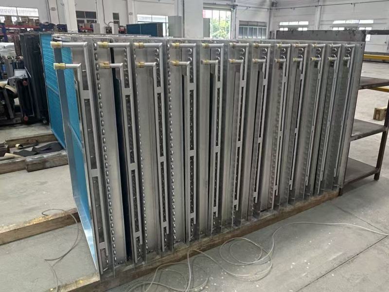
Walk into almost any air handling unit, rooftop system, or commercial greenhouse, and you will find a component quietly doing two opposite jobs: heating air in winter and cooling it in summer. That component is the heating and cooling coil — the dual-function heat exchanger at the heart of hydronic HVAC design. Unlike a dedicated furnace coil or a dedicated chilled water coil, a dual-purpose coil is engineered to switch thermal direction on demand, which makes its internal design fundamentally different from a single-mode coil. This deep dive explains how these coils work in both modes, how multi-row circuiting is engineered, what materials survive years of seasonal cycling, and how Boyi Cooling customizes heating and cooling coils for greenhouses, AHUs, and industrial air handlers worldwide.
Quick Answer
A heating and cooling coil is a finned-tube heat exchanger supplied with hot water, steam, or glycol in heating mode, and chilled water or refrigerant in cooling mode. Heating capacity depends mainly on row count, water temperature, and circuiting; cooling capacity additionally depends on latent (dehumidification) load. The same physical coil can deliver both because forced airflow over tube-and-fin surfaces transfers heat in either direction.
1. One Coil, Two Operating Modes: The Working Principle
At its core, a heating and cooling coil is a counter-flow or cross-flow heat exchanger: copper or stainless tubes carry a working fluid, aluminum (or copper, or stainless) fins multiply the air-side surface area, and a fan drives air across the coil face. What changes between seasons is only the fluid temperature and flow rate — the heat transfer physics stays the same.
1.1 Heating Mode: Hot Water, Steam, or Glycol
In heating mode, the coil receives a hot medium — typically 60–90°C hot water, low-pressure steam, or a propylene/ethylene glycol solution in freezing climates. Heat flows from the tube wall through the fin bond into the airstream, raising supply air temperature by 15–30°C depending on entering conditions. Steam coils face an extra challenge: condensate management. As steam gives up latent heat inside the tubes, condensate must drain continuously or the coil will water-hammer and fail. Proper steam coils therefore use larger tube diameters, sloped headers, and drainable intertube spaces.
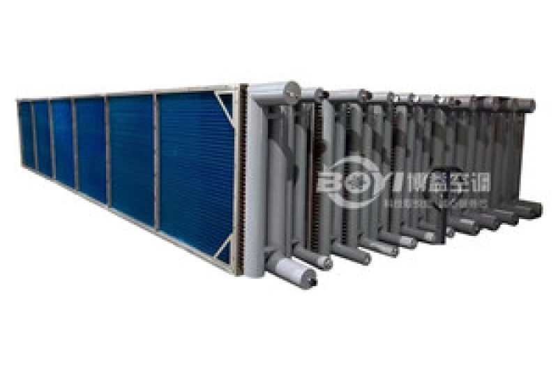
Glycol adds viscosity: a 40% glycol solution carries roughly 15–20% less heat per liter than water and pumps with higher resistance, so coils specified for glycol heating usually need extra rows or higher-velocity circuiting. Boyi Cooling routinely re-optimizes row count and fin spacing when a project switches from water to glycol.
1.2 Cooling Mode: Chilled Water or Direct Expansion
In cooling mode, the same coil is fed with 5–12°C chilled water (or refrigerant in DX configurations). Now the temperature gradient reverses: heat flows from the warm, often humid airstream into the cold tube surface. Cooling duty splits into two parts — sensible cooling (lowering air temperature) and latent cooling (condensing moisture out of the air). The latent fraction is the harder engineering problem, because condensate forms on fins, carries dirt, and must drain cleanly.
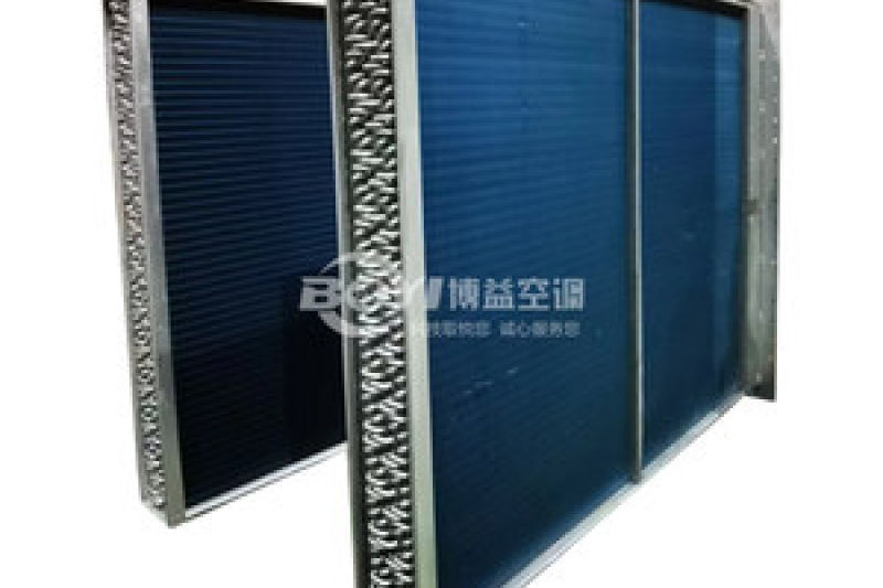
Three cooling-specific design responses follow. First, fin spacing widens: a heating-only coil can run 10–14 fins per inch, while a cooling coil exposed to humid air typically uses 8–12 FPI so condensate does not bridge the fins and choke airflow. Second, the coil must be drainable — vertical tubes or pitched circuits so water exits instead of pooling. Third, face velocity is capped near 500–550 fpm to prevent condensate carryover into ductwork.
| Parameter | Heating Mode | Cooling Mode |
|---|---|---|
| Typical medium | Hot water 60–90°C / steam / glycol | Chilled water 5–12°C / refrigerant |
| Load type | Sensible only | Sensible + latent (dehumidification) |
| Fin density | 10–14 FPI | 8–12 FPI (wider for condensate) |
| Face velocity | Up to 800 fpm | ≤500–550 fpm (carryover limit) |
| Drainage need | Steam condensate traps | Drain pan + sloped fins required |
| Key failure risk | Freeze damage, water hammer | Fin bridging, corrosion, carryover |
2. Multi-Row Configurations: Engineering the Capacity Split
Row count is the primary lever for setting how much heating and cooling capacity one coil frame delivers. Every added row increases surface area roughly linearly, but returns diminish because deeper air passes see reduced temperature difference. In practice:
1–2 Rows
Low sensible duty. Common for preheat or light reheat service, ventilation tempering, and mild-climate heating where the delta-T between medium and air is large.
3–4 Rows
The workhorse range for chilled water cooling with meaningful latent load, and for standard hot water heating in commercial AHUs.
5–6 Rows
Deep cooling with high dehumidification demand, glycol heating, or tight approach temperatures. Watch air-side pressure drop — each row adds fan energy.
The most elegant dual-duty solution is the separate heater + cooler stack: an independent 1-row (or 2-row) heating coil mounted upstream or downstream of a 2-row (or larger) cooling coil. Each coil is then optimized for exactly one job — the heater gets wide fin spacing and freeze-tolerant circuiting, the cooler gets condensate drainage and modest face velocity. Boyi Cooling's greenhouse package pairs precisely this configuration, and it avoids the classic compromise of a single coil that is over-rowed for heating yet under-finned for latent cooling.
3. Where Heating and Cooling Coils Earn Their Keep
Dual-function and paired-coil architectures appear across a wider range of equipment than most buyers expect:
- Air Handling Units (AHUs): the standard hydronic AHU uses a preheat coil, a chilled water cooling coil, and sometimes a reheat coil; dual-purpose coils consolidate inventory in rooftop and packaged systems.
- Rooftop Units: gas-electric or heat-pump RTUs use hydronic coils when a building's boiler and chiller plant serves multiple zones.
- Greenhouses: crops need warm, dry root-zone air at night and cool, humidified air by day — a 1-row heater + 2-row cooler stack handles both without two complete systems.
- Industrial Processes: paint shops, textile lines, and food processing halls demand tight year-round temperature and humidity bands that only engineered coils deliver.
- Commercial Buildings: hospitals, data halls, and laboratories run coils continuously, making drainability and corrosion resistance decisive for service life.
4. Design Considerations Engineers Cannot Ignore
4.1 Circuiting Arrangements
How the tube circuits are piped decides whether the coil actually meets its rating. Counter-flow circuiting (medium entering where air leaves) maximizes the log-mean temperature difference and is standard for heating; parallel-flow suits some cooling duties. Equal circuit lengths keep water velocity uniform across the coil face — a poorly balanced circuit starves some tubes, creating dead zones, uneven leaving-air temperature, and in cooling mode, localized icing.
4.2 Header Design and Drainability
Headers must allow complete drainage for winter shutdown and freeze protection. Drainable headers place the supply connection at the top and return at the bottom with a plug at every low point; non-drainable vented headers are only acceptable where coils are guaranteed to be blown down with compressed air. For cooling service, the condensate-side rule mirrors the water-side rule: fins pitched toward the drain pan, pan sized for peak condensate load, and coil face angled or tube-pitched to carry water off the fin field.
4.3 Freeze Protection
Failed freeze plugs are the most common warranty claim on outdoor-air heating coils. Countermeasures: glycol mixtures, face-and-bypass damper control so air never stratifies across a static coil, embedded-tube steam coils for sub-zero intakes, and controls that interlock pump operation with fan status. Boyi Cooling builds winterized coil packages with downflow-preventing baffles and optional freeze-stat provisions for cold-region projects.
4.4 Air-Side Pressure Drop and Fan Energy
Every row, every extra fin per inch, and every protective coating adds pressure drop. Fan power scales linearly with static pressure, so a casually chosen coil can silently add kilowatts for decades. Good practice budgets the coil pressure drop early and lets the manufacturer trade row count against fin height to hit the target.
5. Material Selection for Dual-Use Duty
Because a dual-purpose coil lives through hot dry cycles and cold condensing cycles, material choice weighs thermal performance against cycling durability and the environment it breathes:
| Combination | Best For | Trade-offs |
|---|---|---|
| Copper tube + aluminum fin | General HVAC, greenhouses, AHUs — the efficiency default | Vulnerable to aggressive coastal/chemical air; protective coating needed |
| Copper tube + copper fin | Humid, corrosive or washdown environments | Higher cost; slightly lower fin efficiency than aluminum |
| Stainless tube + stainless fin | Chemical plants, food processing, marine air, high-temperature steam | Lower thermal conductivity demands more surface area (deeper coils) |
| Coated Cu/Al (e-coat, epoxy, GoldFin) | Coastal, industrial, or high-humidity dual-mode duty | Adds cost and typically 0.5–1.5% thermal penalty |
For most greenhouse and commercial AHU projects, Boyi Cooling recommends copper tube with aluminum fin as the value baseline, stepping up to full copper or stainless only where the intake air chemistry justifies it. Where budget drives the decision, an engineered coil selection with wider fin spacing often beats a thinner coil with premium fins.
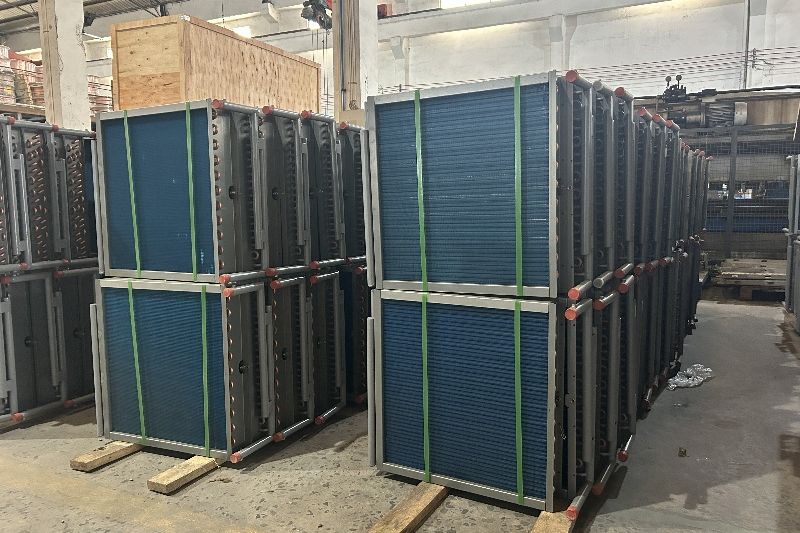
6. Case Study: Greenhouse Heating and Cooling on One Coil Stack
A commercial greenhouse grower approached Boyi Cooling with a seasonal bottleneck: winter nights demanded warm air for seedling benches, while midday summer sun pushed canopy temperatures past tolerable limits. Installing two independent systems doubled capital cost, controls complexity, and roof penetrations.
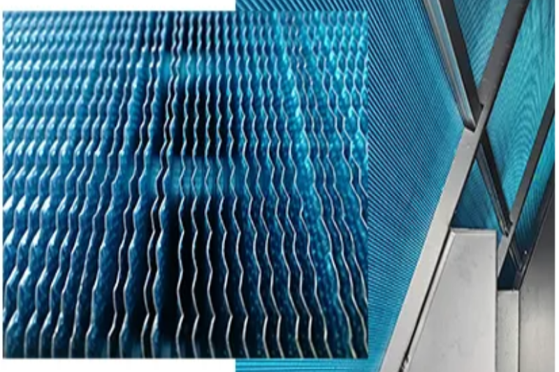
The delivered solution was a custom 1-row heater and 2-row cooler pair engineered as one interchangeable module. The 1-row heating coil, fed by the site's hot water loop, provides gentle bulk warming with minimal fan penalty; the 2-row cooling coil handles summertime sensible cooling and light dehumidification with wide, condensate-friendly fin spacing. Both coils share identical frame dimensions and flange patterns, so a single casing, one fan, and one controls loop serve both seasons. Results reported by the grower: roughly 30% lower installed cost than two separate systems, faster seasonal changeover, and stable root-zone temperatures across the shoulder seasons when greenhouses swing hardest.
The same architecture scales up: Boyi regularly customizes heater/cooler stacks for custom AHU and process-air applications, from pharmaceutical cleanrooms to livestock ventilation, adjusting rows, circuiting, and materials per project.
7. Performance Optimization: How Circuiting Sets the Capacity Ratio
A dual-purpose coil's heating and cooling ratings are not independent — both flow from the same geometry, and the split between them is tuned by circuiting. Three levers matter most:
- Pass arrangement: more passes raise water velocity and the inside film coefficient, boosting capacity per row — critical when a coil must heat hard with only 1–2 rows.
- Flow direction: counter-flow maximizes heating delta-T; cooling coils are circuited to keep the coldest surface where latent removal is highest.
- Velocity limits: heating tolerates 2–4 ft/s tube velocity; chilled water coils cap near 2–6 ft/s to control erosion and pressure drop.
In practice, the engineer fixes the harder duty (usually cooling with latent load), then verifies heating performance and tunes passes or supply temperature to close the gap. A capable manufacturer runs both rating conditions in selection software before fabrication — Boyi Cooling includes dual-mode performance data with every dual-duty coil quotation, so buyers can check the capacity ratio against their controls strategy before committing.
Why Partner with Boyi Cooling
20+ Years of Thermal Engineering
Two decades of finned-tube design experience across dry coolers, condensers, evaporators, and custom HVAC coils.
Fully Customized Manufacturing
Rows, circuiting, headers, fin density, materials, and coatings are all configurable to your exact duty and casing envelope.
Exported to 30+ Countries
Proven delivery to projects across Europe, the Middle East, Southeast Asia, and the Americas, with export-grade packaging.
Dual-Mode Performance Data
Every dual-duty coil ships with verified heating and cooling ratings so your selection is documented, not estimated.
Frequently Asked Questions
Can one coil truly provide both heating and cooling?
Yes, provided the two duties share compatible row counts and circuiting. Many projects instead pair a dedicated 1-row heater with a 2-row cooler in one casing, which removes the capacity compromise while keeping a single air path. Both approaches are standard; the choice depends on how far apart your heating and cooling duties are.
Why does the cooling mode need wider fin spacing than heating?
Because cooling coils condense moisture. With 12+ fins per inch, condensate bridges the fin gaps, blocks airflow, and raises pressure drop. Wide spacing (8–12 FPI) plus a properly pitched drain pan keeps water moving off the coil instead of carrying over into the duct.
How do I prevent freeze damage to a heating coil on the outdoor-air intake?
Combine measures: use glycol where the climate demands it, install face-and-bypass dampers so cold air never stratifies across a static coil, interlock pumps with fan status, and specify drainable headers so the coil can be emptied for shutdown. For sub-zero steam applications, ask for an embedded-tube or tube-in-tube steam coil design.
Key Takeaways
- A heating and cooling coil swaps medium temperature, not physics — counter-flow finned-tube heat exchange works in both directions.
- Cooling duty is harder to engineer: latent load, condensate drainage, and carryover limits dictate fin spacing and face velocity.
- Row count and circuiting are the levers that set the heating/cooling capacity ratio; 1-row heater + 2-row cooler stacks resolve extreme splits.
- Material choice follows the air the coil breathes — copper/aluminum as default, full copper or stainless for corrosive duty.
- Boyi Cooling custom-builds dual-duty coil stacks for greenhouses, AHUs, and industrial air handlers, backed by 20+ years of experience and exports to 30+ countries.
Need a Custom Heating & Cooling Coil for Your HVAC System?
Send us your airflow, medium temperatures, and duty requirements — Boyi Cooling's engineers will return a dual-mode coil selection with performance data and drawings.
Contact Our Engineering Team About Boyi Cooling