Fin Tube Heat Exchanger Design: Understanding Fin Density, Spacing, and Surface Area
- Share
- publisher
- Boyi Cooling
- Issue Time
- Oct 23,2026
Summary
Fin design is the heart of every air-cooled heat exchanger. This guide explains how fin type, fin density (FPI), fin spacing, tube patterns and fin material determine heat transfer, airside pressure drop and fouling resistance. Learn practical rules for clean versus dusty environments, how effective surface area is calculated, and the most common design mistakes to avoid — from Boyi Cooling, a custom coil manufacturer with 20+ years of experience serving customers in over 30 countries.
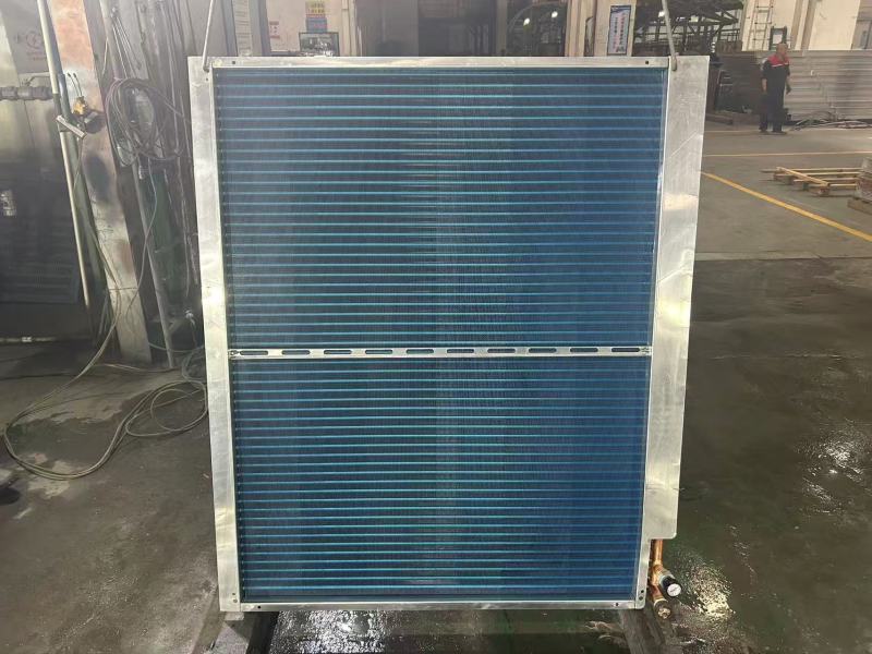
When buyers compare heat exchangers, they usually focus on tube material, cooling capacity, or footprint. Yet the true performance differentiator of any air-cooled heat exchanger is the fin design. Fins multiply the surface area available for heat transfer, and decisions about fin geometry, fin density, fin spacing, and tube arrangement ripple through every aspect of performance — capacity, airside pressure drop, fan power, fouling behavior, and ultimately total cost of ownership. In this guide, the engineering team at Boyi Cooling breaks down the core variables of fin tube heat exchanger design, so that buyers, consultants, and OEM engineers can read a coil spec sheet with confidence and know exactly which questions to ask before placing an order.
1. Why Fin Design Is the Heart of Heat Exchanger Performance
In a typical finned tube heat exchanger, a hot liquid or refrigerant flows inside the tubes while ambient air passes over the outside. The problem: air is a poor heat transfer medium — its heat transfer coefficient is 20 to 50 times lower than that of water or refrigerant flowing inside the tube. Without fins, an air-cooled coil would need an impractical amount of tube length to reject the same heat.
Fins solve this imbalance by dramatically expanding the airside surface area. A well-designed finned coil can achieve 15 to 25 times more external surface area than a bare tube bundle of the same face area. But this multiplication is not free: more fin surface also means more air resistance, more fan power, and more places for dust and contamination to accumulate. The entire discipline of fin tube design is therefore a controlled trade-off between heat transfer gain and airside penalty.
2. Fin Types: Plain, Wavy, Louvered, and Slit Fins
Fin manufacturers offer several standardized fin geometries, each with a distinct performance personality. Choosing among them is the first major design decision.
Plain Fins
Smooth, uninterrupted surfaces. Lowest airside pressure drop and excellent fouling resistance, but the most modest heat transfer enhancement. Ideal for dusty, dirty airstreams such as mining sites and heavy industry.
Wavy Fins
Corrugated surfaces that repeatedly redirect the airflow, inducing turbulence between fins. A strong all-round performer: noticeably better heat transfer than plain fins with only a moderate pressure drop increase. Widely used in dry coolers and condenser coils.
Louvered Fins
Louvered fins cut into the boundary layer with angled slats, delivering the highest heat transfer coefficient per unit area. The trade-off is higher pressure drop and greater fouling sensitivity, which suits clean, well-maintained environments.
Slit Fins
Small slits punched into the fin surface to periodically break and restart the air boundary layer. Efficient in compact coils where face area is limited, but they should be avoided wherever airborne fibers or dust are present.
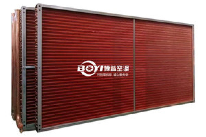
As a rule of thumb: the more aggressive the fin surface enhancement, the cleaner the air must be. Louvered and slit fins reward clean data centers and HVAC rooms; plain and wavy fins survive desert dust, agricultural environments, and industrial exhaust. Boyi Cooling manufactures all four fin families in-house and matches geometry to the site's air quality profile rather than defaulting to a single catalog design.
3. Fin Density (FPI): How Fins per Inch Change Everything
Fin density is expressed in fins per inch (FPI). It is arguably the single most influential specification on a coil datasheet, because it simultaneously controls three things: total surface area, heat transfer rate, and airside resistance.
| Fin Density | Typical Range | Surface Area | Airside Pressure Drop | Best Suited For |
|---|---|---|---|---|
| Low | 6–10 FPI | Low | Very low | Dusty / fouling environments, large fin spacing requirements |
| Medium | 10–14 FPI | Moderate | Moderate | General industrial cooling, dry coolers, most HVAC duties |
| High | 14–20+ FPI | High | High | Clean air, compact footprints, low temperature approach requirements |
Two misconceptions deserve attention. First, doubling fin density does not double capacity. As fins get closer together, the air velocity through the fin channels drops for the same fan, airflow maldistribution increases, and the effectiveness of each square meter of added surface declines. Second, high fin density increases cleaning difficulty — a coil specified at 18 FPI in a cottonwood or dust-laden environment may lose more capacity to fouling within a year than it ever gained from the extra surface.
For most industrial dry cooler and condenser applications, 10 to 14 FPI with a wavy or plain fin hits the sweet spot. Higher densities are justified in clean indoor conditions or where equipment footprint is severely constrained.
4. Fin Spacing: Clean Environments vs. Dusty Environments
Fin spacing is the physical counterpart of fin density — the clear distance between adjacent fins. While density defines performance, spacing defines survivability in the face of contamination.
In clean environments — climate-controlled data centers, pharmaceutical cleanrooms, indoor process plants — tight spacing is safe and allows high surface area within a compact casing. In dusty or fibrous environments — mining operations, agricultural greenhouses, deserts, textile mills, and sites near unpaved roads — tight spacing becomes a liability. Dust bridges between fins, forms an insulating mat, and can choke airflow entirely. Frost and condensation further narrow the gaps in low-temperature applications.
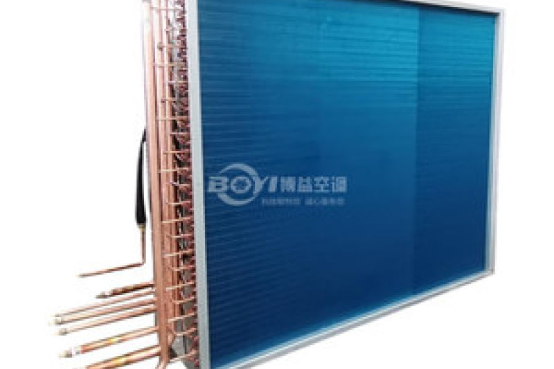
Practical guidelines Boyi Cooling applies during coil selection:
- ≥ 3 mm spacing for heavy dust, fibrous, or high-humidity frosting conditions
- 2–3 mm spacing for general outdoor industrial installations with periodic cleaning
- < 2 mm spacing only where the airstream is filtered and the maintenance regime is reliable
Boyi Cooling's greenhouse and mining projects are instructive examples: coils shipped to these sectors are deliberately specified with wider fin spacing and plain or wavy fins, even when the "catalog efficiency" of a denser coil looks better on paper. Over a five-year service life, the wider-spaced coil delivers more average capacity because it stays clean.
5. Tube Patterns: Inline vs. Staggered Arrangements
Beneath the fins, the way tubes are arranged shapes how air actually moves through the coil.
Inline Pattern
Tubes aligned in straight rows create low-resistance air lanes. Pressure drop and fan energy are lower, but air can "channel" between rows and bypass tube surfaces, reducing the effective heat transfer of downstream rows.
Staggered Pattern
Alternate rows offset by half a tube pitch force air to sweep across each tube, repeatedly disrupting the boundary layer. Heat transfer per row improves by roughly 20–40% over inline at equal air velocity, at the cost of 30–60% higher airside pressure drop.
Staggered arrangements dominate high-performance coils where footprint matters; inline arrangements suit low-pressure-drop designs and systems with marginal fan capacity. In multi-row deep coils, Boyi Cooling frequently applies a hybrid approach — staggered entry rows to establish good air distribution, followed by inline rows to cap the total pressure drop.
6. Surface Area Calculation: What "Total Surface Area" Really Means
Coil datasheets quote a total external surface area, usually in square meters. It is the sum of two components:
Where Atube is the exposed tube surface between fins, Afin is the full fin surface, and ηfin is the fin efficiency — the fraction of the fin surface that actually operates near the tube wall temperature. Fin efficiency typically falls between 0.7 and 0.95, and it depends on fin material, thickness, and height. A taller or thicker fin made of low-conductivity material carries a temperature gradient along its own height, so its tip does less work than its base.
This is why raw surface area can mislead. A coil quoting 200 m² with aluminum fins at 0.8 efficiency delivers roughly the same effective area as a coil quoting 160 m² with copper fins at 0.95 efficiency. Buyers comparing quotes should always ask for effective (weighted) surface area, not just the geometric figure.
For buyers evaluating complete systems rather than individual coils, Boyi Cooling's dry cooler product range documents both fin specification and tested capacity for every model, so the numbers can be compared on a like-for-like basis.
7. Fin Material: Copper vs. Aluminum vs. Stainless Steel
Fin material determines thermal conductivity, weight, cost, and corrosion behavior.
Copper Fins
Thermal conductivity around 385 W/m·K — roughly double that of aluminum. Highest fin efficiency, best for compact high-performance coils and refrigerant condensers. Higher material cost and softer surface during handling.
Aluminum Fins
Conductivity near 205 W/m·K with about one-third the density of copper. The industry default for dry coolers and condensers: excellent performance-to-cost ratio, light weight, and compatible with epoxy, hydrophilic, and electrophoretic coatings.
Stainless Steel Fins
Conductivity around 16 W/m·K demands more fin surface for the same duty, but delivers unmatched resistance to corrosive atmospheres — coastal salt fog, chemical plants, and flue gas recovery. Frequently paired with stainless tubes for full-corrosion-resistance coils.
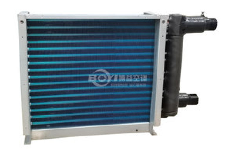
For aggressive environments, the material decision outweighs every other fin parameter. Boyi Cooling's stainless steel fin coil series, engineered for chemical and coastal installations, trades modest thermal performance for decades of corrosion-free service — a trade that consistently proves economical in total cost of ownership terms.
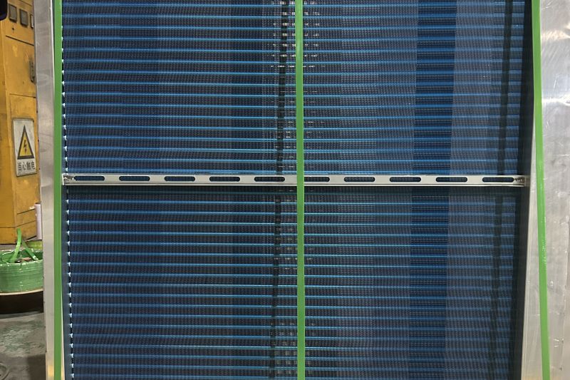
BOYI Customized 1-Row Heater and 2-Rows Cooler for Greenhouse Cultivation
Custom finned tube coil combining a single-row heating circuit and a two-row cooling circuit for greenhouse climate control. Wide fin spacing resists dust and humidity, while the copper tube aluminum fin construction delivers reliable heat transfer season after season. Manufactured to order in Boyi Cooling's 20,000 m² facility.
View Product Details8. Optimization in Practice: How Boyi Cooling Selects Fin Parameters
None of these variables should be chosen in isolation — and in practice they never are. Boyi Cooling's engineering team uses coil selection and simulation software that iterates fin type, density, tube pattern, row depth, and face velocity against the customer's duty point: flow rate, entering and leaving temperatures, available fan pressure, ambient design conditions, and air quality. The software outputs candidate designs ranked by capacity margin, airside pressure drop, material cost, and predicted fouling behavior.
The process typically converges within two to three iterations. A representative example from a recent greenhouse project: the initial catalog selection at 12 FPI delivered the required 180 kW but with fan pressure that exceeded the available AHU budget. By switching to a wavy fin at 10 FPI with a staggered tube pattern, the design recovered the capacity within the same casing while cutting airside pressure drop by 22% — a change invisible on the datasheet headline but decisive for the customer's operating cost.
This selection capability is backed by more than 20 years of thermal engineering experience, a 20,000 m² custom manufacturing plant, and coil shipments to over 30 countries across data center, mining, chemical, greenhouse, and HVAC sectors. Whether the requirement is a single replacement coil or an OEM production series, each design is calculated rather than copied. Buyers who want to walk through the selection logic for their own duty can start via the online inquiry form with their flow, temperatures, and site conditions.
9. Common Fin Design Mistakes — and How to Avoid Them
Over-Finning
Specifying maximum fin density to chase capacity, then losing it all to fouling, airflow maldistribution, and fan oversizing. Always validate FPI against the site's air quality and cleaning regime.
Under-Sizing the Coil
Compressing the required surface area into too few rows or too small a face area, which forces high face velocities, high pressure drop, and noise. Capacity margin of 5–10% at design ambient is standard good practice.
Ignoring the Fouling Factor
Quoting performance on clean-coil data alone. A realistic fouling allowance — or a wider fin spacing from the start — protects the customer's capacity in year three, not just at commissioning.
Comparing Quotes on Geometry Alone
Two coils with identical face dimensions and FPI can differ by 15% in effective surface area due to fin efficiency and material. Demand tested or calculated capacity at the same duty point instead.
Frequently Asked Questions
What fin density is best for a dusty environment?
For mining, desert, agricultural, or fibrous airstreams, 6–10 FPI with wide spacing (≥ 3 mm) and plain or wavy fins is the robust choice. High-density fins should be reserved for filtered or indoor air.
Does higher fin density always mean more heat transfer?
No. Beyond an application-specific limit, added fins raise pressure drop faster than they add usable surface, reduce inter-fin air velocity, and accelerate fouling. Capacity can actually decrease at very high FPI for a fixed fan.
Can fin material be mixed with different tube materials?
Yes — the most common combination is copper tubes with aluminum fins. For corrosive duties, stainless steel tubes with stainless steel fins, or coated aluminum fins with galvanized or stainless casings, are recommended. Galvanic compatibility should always be checked.
Key Takeaways
- Fin design controls the balance between heat transfer, airside pressure drop, and fouling tolerance — it is the heart of air-cooled heat exchanger performance.
- Match fin type and density to air quality: aggressive fins for clean air, plain or wavy fins with wide spacing for dust.
- Compare coils on effective surface area and tested capacity, not raw geometry.
- Work with a manufacturer that calculates the selection for your duty point — Boyi Cooling has done so for customers in over 30 countries for more than 20 years.
Need a Fin Tube Heat Exchanger Calculated for Your Application?
Send Boyi Cooling your flow rate, temperatures, and site conditions — our engineers will return a calculated coil selection with fin specification, pressure drop, and pricing.
Contact Our Engineering Team