8 Key Design Parameters for Optimizing Finned Tube Heat Exchangers
- Share
- publisher
- Sam Chang
- Issue Time
- Jun 26,2025
Summary
Finned tube heat exchangers, as highly efficient thermal exchange equipment, are widely used in refrigeration, HVAC, chemical engineering, and many other fields. The rationality and scientific rigor of their design directly determine heat exchange efficiency, equipment performance, and service life. When designing a finned tube heat exchangers, there are eight key parameters that require special attention.
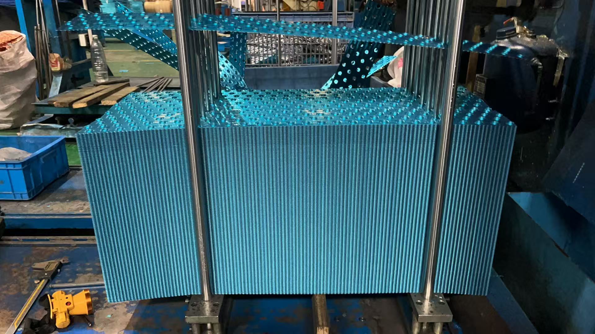
Discover how to enhance heat transfer efficiency and performance in HVAC heat exchangers and industrial heat exchangers with these expert insights. A finned tube heat exchanger is a highly efficient device used for transferring heat between fluids, such as air-to-liquid or gas-to-liquid. Its design, featuring tubes with attached fins, increases the surface area for heat transfer efficiency. These exchangers are critical in applications like HVAC heat exchangers, refrigeration systems, power plants, and chemical processing. For example, in air conditioning, they cool or heat air to maintain optimal system performance. Optimizing heat exchanger design enhances heat transfer efficiency, reduces pressure drop, and lowers operational costs. Studies show that precise adjustments to design parameters can improve performance by 10-20%. For industrial heat exchangers and HVAC heat exchangers, balancing performance and cost is essential for high-load operations. Cross-section of a finned tube heat exchanger showing key components. The choice of fin material significantly impacts heat transfer efficiency and durability. Aluminum (237 W/m·K) is lightweight and cost-effective, ideal for HVAC heat exchangers, while copper offers superior conductivity and corrosion resistance for high-temperature industrial heat exchangers. Consider corrosion resistance and cost when selecting fin material. Fin height affects the heat transfer area and pressure drop. High-fin designs enhance heat transfer efficiency but may increase flow resistance. Low-fin designs are suited for low-pressure-drop applications. Optimal ranges (e.g., 5-10mm) depend on the specific use case in industrial heat exchangers. Fin spacing balances heat transfer area and flow resistance. Tighter spacing boosts heat transfer efficiency but increases pressure drop. Studies suggest 2-4mm spacing for HVAC heat exchangers, while wider spacing suits industrial heat exchangers. CFD simulations can optimize fin spacing. Types of fins: plain, wavy, and louvered for heat exchanger design. Fin thickness influences structural integrity and heat transfer efficiency. Thicker fins (e.g., 0.5mm) ensure durability in harsh environments, while thinner fins (e.g., 0.2mm) reduce costs for lighter applications. Choose thickness based on operational conditions in your heat exchanger design. Tube material selection is critical for performance. Copper is common in HVAC heat exchangers due to its high conductivity, while stainless steel suits corrosive fluid environments in industrial heat exchangers. Select materials based on fluid type and operating conditions. Tube diameter impacts fluid flow and heat transfer efficiency. Smaller diameters (e.g., 10mm) are ideal for compact HVAC heat exchangers, while larger diameters (e.g., 25mm) support higher flow rates in industrial heat exchangers. Optimize tube diameter for efficiency. Tube arrangement (inline or staggered) affects flow and heat transfer efficiency. Staggered layouts increase turbulence, improving heat exchanger performance, but may raise pressure drop. CFD modeling optimizes tube arrangement for specific applications. Baffle design controls shell-side flow and pressure drop. A 20% baffle cut (Delaware method) optimizes flow in industrial heat exchangers. Effective baffle design enhances heat exchanger performance by minimizing dead zones. Comparison of fin material properties for heat exchanger design. Leverage studies on clearance and fin geometry to minimize pressure drop while maximizing heat transfer efficiency. For example, wavy or perforated fins can reduce resistance by 10-15% in high-flow HVAC heat exchangers. Tools like SolidWorks, HTRI, or ANSYS CFX enable precise modeling of heat exchanger designs. These tools simulate fluid flow and heat transfer efficiency, optimizing fin material selection and tube arrangement. CFD simulation visualizing heat exchanger performance. Experimental testing with manufacturer data calibration ensures heat exchanger performance meets design expectations, especially for industrial heat exchangers in demanding environments. High pressure drop in finned tube heat exchangers can be mitigated using wavy or perforated fins to reduce flow resistance while maintaining heat transfer efficiency. Use coatings or corrosion-resistant materials like stainless steel in industrial heat exchangers to extend service life in corrosive environments. Multi-objective optimization (e.g., NSGA-II) balances cost and heat exchanger performance, ensuring cost-effective heat exchanger designs. Optimizing these eight parameters is crucial for designing high-performance finned tube heat exchangers. By applying these insights, you can enhance heat transfer efficiency and reduce costs in HVAC heat exchangers and industrial heat exchangers. Contact Boyi Cooling’s experts for tailored heat exchanger design solutions. The importance varies by application, but fin material selection and tube arrangement are often critical for balancing heat transfer efficiency and durability. Consider thermal conductivity, corrosion resistance, and cost. Aluminum is ideal for HVAC heat exchangers, while copper suits high-temperature industrial heat exchangers. Yes, tools like ANSYS CFX enhance heat exchanger design accuracy by simulating flow and heat transfer efficiency, reducing costly errors.8 Key Design Parameters for Optimizing Finned Tube Heat Exchangers
Understanding Finned Tube Heat Exchangers
What Are Finned Tube Heat Exchangers?
Why Heat Exchanger Design Optimization Matters

The 8 Critical Design Parameters
1. Fin Material Selection
2. Fin Height
3. Fin Spacing

4. Fin Thickness
5. Tube Material
6. Tube Diameter
7. Tube Arrangement
8. Baffle Design
Material
Thermal Conductivity (W/m·K)
Cost
Corrosion Resistance
Aluminum
237
Low
Moderate
Copper
401
High
High
Practical
Tips for Optimizing Your Heat Exchanger Design
Balancing Heat Transfer Efficiency and Pressure Drop
Leveraging Software Tools

Testing and Validation
Common Challenges and Solutions
High Pressure Drop
Material Corrosion
Cost Constraints
Conclusion
FAQs
What is the most important design parameter for finned tube heat exchangers?
How do I choose the right fin material?
Can software improve heat exchanger design accuracy?