Key points for selection of various coil types in heat exchangers
- Share
- publisher
- Sam Chang
- Issue Time
- May 23,2025
Summary
Key points for selection of various coil types in heat exchangers.
Key points for selecting chilled and hot water coils
1. For general combined air handling unit coils, the face velocity of the coil should be controlled below 2.5 m/s without using a drift eliminator. If a drift eliminator is adopted, the face velocity of the coil should be designed at 3.0 - 3.2 m/s, and the face velocity of the coil should not exceed 3.5 m/s.
2. The flow velocity in the tube passes of chilled and hot water coils should be controlled within the range of 0.6 to 1.5 m/s, and the tube pass resistance of the coils should be kept below 50 kPa. The same applies to dry coolers.
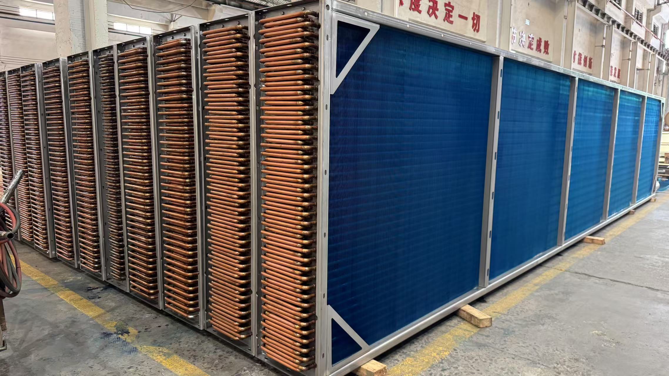
3. The standard fin thickness for 5/8” coil tubes is 0.145 mm, with a standard fin spacing of 3.2 mm, and the standard fin type is sine wave corrugated fins.
For 1/2” coil tubes, the standard fin thickness is 0.145 mm, with a standard fin spacing of 2.5 mm, and the standard fin type is flat knife louvered fins.
For 3/8” coil tubes, the standard fin thickness is 0.115 mm (hydrophilic aluminum fins), with a standard fin spacing of 2.3 mm, and the standard fin type is flat knife louvered fins.
Key points for steam coil selection
1. The face velocity of steam coils should not exceed 5 m/s, with a maximum of 2 rows.
2. The steam pressure should be controlled within the range of 0.1-0.4 MPa.
3. When the steam coil pressure is too high, the vacuum method can be used to reduce heat transfer capacity.
4. The outer pipe of the steam coil uses a 15.88*0.8mm smooth copper tube, and the inner pipe uses a 9.2*0.3mm smooth copper tube.
Key points for the selection of evaporation coils
1. For circulating units, the face velocity should not exceed 2.2 m/s, and the number of rows should not exceed six. For fresh air units, the face velocity should not exceed 2.0 m/s, and the number of rows should not exceed six. The circuit arrangement should adopt a bottom-inlet and top-outlet configuration with counterflow. During minimum cooling operation, the maximum face area should be covered as much as possible, and each refrigeration circuit should be arranged as symmetrically as possible.
2. The evaporation temperature should be controlled between 4-7°C, and the suction superheat should be maintained between 5-10°C.
3. The resistance of the refrigerant in the evaporator is normally controlled between 0.3-0.6 bar, with a maximum allowable limit not exceeding 1 bar.
4. The water passage rate of the evaporator should comprehensively consider the circuit arrangement of the heat exchanger and oil return. Under normal circumstances, for a single-compressor refrigeration system, each circuit should be 1 HP. For dual-compressor or multi-compressor refrigeration systems, it is necessary to ensure that the refrigeration capacity of each circuit is not less than 1 HP.
Fin type
A. Flat Louver (Flat Blade Louver)
B. Corrugated Curved Louver (Corrugated Opening Blade)
C. Dot-patterned Corrugated Blade (Dot-patterned Windowed Blade)
D. Plain Blade Without Windows